- 您现在的位置:买卖IC网 > Sheet目录475 > MAX9996ETP+D (Maxim Integrated)IC MIXER DOWN CONV 20-TQFN
�� �
�
�SiGe� High-Linearity,� 1700MHz� to� 2200MHz�
�Downconversion� Mixer� with� LO� Buffer/Switch�
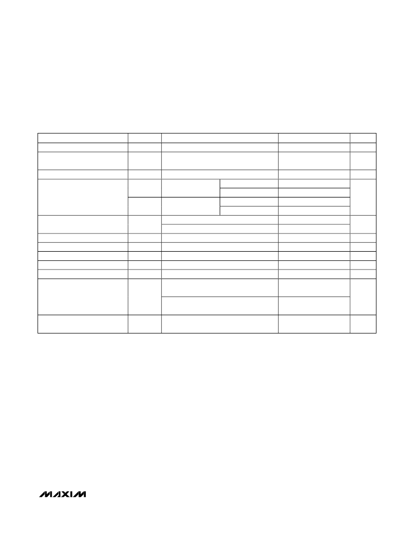
�AC� ELECTRICAL� CHARACTERISTICS� (continued)�
�(MAX9996� Typical� Application� Circuit� ,� V� CC� =� +4.75V� to� +5.25V,� RF� and� LO� ports� are� driven� from� 50� ?� sources,� P� LO� =� -3dBm� to�
�+3dBm,� P� RF� =� -5dBm,� f� RF� =� 1700MHz� to� 2200MHz,� f� LO� =� 1900MHz� to� 2400MHz,� f� IF� =� 200MHz,� f� LO� >� f� RF� ,� T� C� =� -40°C� to� +85°C,�
�unless� otherwise� noted.� Typical� values� are� at� V� CC� =� +5V,� P� RF� =� -5dBm,� P� LO� =� 0dBm,� f� RF� =� 1900MHz,� f� LO� =� 2100MHz,� f� IF� =� 200MHz,�
�T� C� =� +25°C,� unless� otherwise� noted.)� (Notes� 1,� 2)�
�PARAMETER�
�Noise� Figure�
�SYMBOL�
�NF�
�CONDITIONS�
�Single� sideband�
�MIN�
�TYP�
�9.7�
�MAX�
�UNITS�
�dB�
�Noise� Figure� Under-Blocking�
�LO� Drive�
�P� RF� =� 5dBm,� f� RF� =� 2000MHz,�
�f� LO� =� 2190MHz,� f� BLOCK� =� 2100MHz� (Note� 5)�
�-3�
�19�
�+3�
�dB�
�dBm�
�Spurious� Response� at� IF�
�2x2�
�3x3�
�2LO-2RF�
�3LO-3RF�
�P� RF� =� -10dBm�
�P� RF� =� -5dBm�
�P� RF� =� -10dBm�
�P� RF� =� -5dBm�
�72�
�67�
�87�
�77�
�dBc�
�LO1� to� LO2� Isolation�
�Maximum� LO� Leakage� at� RF� Port�
�Maximum� LO� Leakage� at� IF� Port�
�Minimum� RF-to-IF� Isolation�
�LO� Switching� Time�
�RF� Port� Return� Loss�
�LO2� selected,� 1900MHz� <� f� LO� <� 2100MHz�
�LO1� selected,� 1900MHz� <� f� LO� <� 2100MHz�
�P� LO� =� +3dBm�
�P� LO� =� +3dBm�
�50%� of� LOSEL� to� IF� settled� to� within� 2� °�
�49�
�43�
�-20�
�-30�
�40�
�50�
�15�
�dB�
�dBm�
�dBm�
�dB�
�ns�
�dB�
�LO� Port� Return� Loss�
�LO1/2� port� selected,�
�LO2/1� and� IF� terminated�
�LO1/2� port� unselected,�
�LO2/1� and� IF� terminated�
�16�
�26�
�dB�
�IF� Port� Return� Loss�
�LO� driven� at� 0dBm,� RF� terminated� into� 50� ?� ,�
�differential� 200� ?�
�20�
�dB�
�Note� 1:�
�Note� 2:�
�Note� 3:�
�Note� 4:�
�Note� 5:�
�Guaranteed� by� design� and� characterization.�
�All� limits� include� external� component� losses.� Output� measurements� taken� at� IF� output� of� the� Typical� Application� Circuit� .�
�Operation� outside� this� range� is� possible,� but� with� degraded� performance� of� some� parameters.�
�Compression� point� characterized.� It� is� advisable� not� to� operate� continuously� the� mixer� RF� input� above� +12dBm.�
�Measured� with� external� LO� source� noise� filtered� so� the� noise� floor� is� -174dBm/Hz.� This� specification� reflects� the� effects� of� all�
�SNR� degradations� in� the� mixer,� including� the� LO� noise� as� defined� in� Maxim� Application� Note� 2021.�
�_______________________________________________________________________________________�
�3�
�发布紧急采购,3分钟左右您将得到回复。
相关PDF资料
MAX9996EVKIT
EVAL KIT FOR MAX9996
MC-7831-AZ
IC PUSH-PULL AMP 870MHZ H02
MC-7832-AZ
IC PUSH-PULL AMP 870MHZ H02
MC-7833-AZ
IC PUSH-PULL AMP 870MHZ H02
MC-7834-KC-AZ
IC PUSH-PULL AMP 870MHZ H02
MC-7845-AZ
IC AMPLIFIER DBL 870MHZ H02
MC-7846-AZ
IC AMPLIFIER DBL 870MHZ H02
MC-7847-KC-AZ
IC AMPLIFIER DBL 870MHZ H02
相关代理商/技术参数
MAX9996ETP+G48
制造商:Rochester Electronics LLC 功能描述: 制造商:Maxim Integrated Products 功能描述:
MAX9996ETP+T
功能描述:上下转换器 SiGe 1700-2200MHz Downconversion Mixer RoHS:否 制造商:Texas Instruments 产品:Down Converters 射频:52 MHz to 78 MHz 中频:300 MHz LO频率: 功率增益: P1dB: 工作电源电压:1.8 V, 3.3 V 工作电源电流:120 mA 最大功率耗散:1 W 最大工作温度:+ 85 C 安装风格:SMD/SMT 封装 / 箱体:PQFP-128
MAX9996ETP+TD
功能描述:上下转换器 SiGe 1700-2200MHz Downconversion Mixer RoHS:否 制造商:Texas Instruments 产品:Down Converters 射频:52 MHz to 78 MHz 中频:300 MHz LO频率: 功率增益: P1dB: 工作电源电压:1.8 V, 3.3 V 工作电源电流:120 mA 最大功率耗散:1 W 最大工作温度:+ 85 C 安装风格:SMD/SMT 封装 / 箱体:PQFP-128
MAX9996ETP-T
功能描述:射频混合器 RoHS:否 制造商:NXP Semiconductors 频率范围: 转换损失——最大: 工作电源电压:6 V 最大工作温度:+ 85 C 最小工作温度:- 40 C 安装风格:Through Hole 封装 / 箱体:PDIP-8 封装:Tube
MAX9996EVKIT
功能描述:射频开发工具 RoHS:否 制造商:Taiyo Yuden 产品:Wireless Modules 类型:Wireless Audio 工具用于评估:WYSAAVDX7 频率: 工作电源电压:3.4 V to 5.5 V
MAX999AAUK+
制造商:Maxim Integrated Products 功能描述:
MAX999AAUK+T
功能描述:校验器 IC Single uPower Comparator RoHS:否 制造商:STMicroelectronics 产品: 比较器类型: 通道数量: 输出类型:Push-Pull 电源电压-最大:5.5 V 电源电压-最小:1.1 V 补偿电压(最大值):6 mV 电源电流(最大值):1350 nA 响应时间: 最大工作温度:+ 125 C 安装风格:SMD/SMT 封装 / 箱体:SC-70-5 封装:Reel
MAX999EUK
制造商:Maxim Integrated Products 功能描述:5 PIN COUNT SOT PACKAGE TYPE - Rail/Tube 制造商:Maxim Integrated Products 功能描述:COMPARATOR HIGH SPEED SMD SOT235